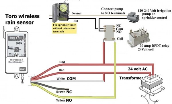
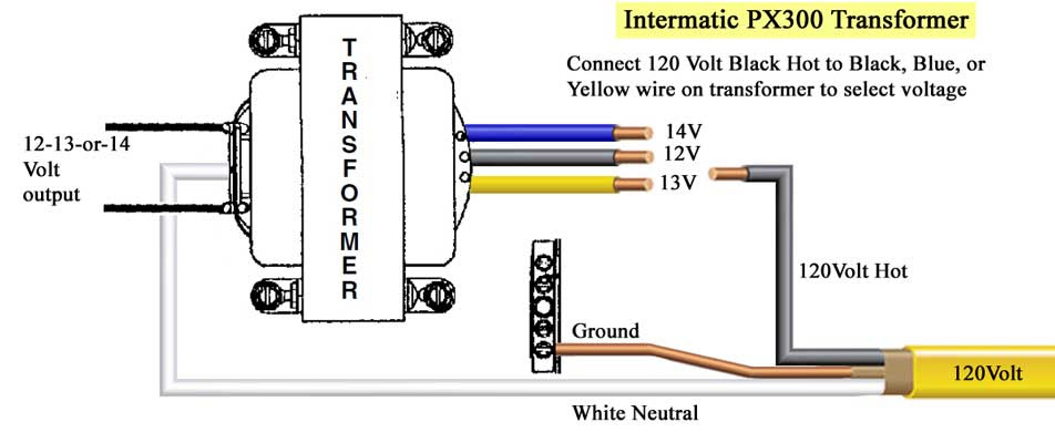
120v 24v Coil Transformer Wiring Diagram
120v potential transformer the wiring diagram on the opposite hand is particularly beneficial to an outside electrician. View profile view forum posts diamond join date dec 2002 location monterey bay, california posts 10,260 post thanks / like likes (given) 28 likes (received).
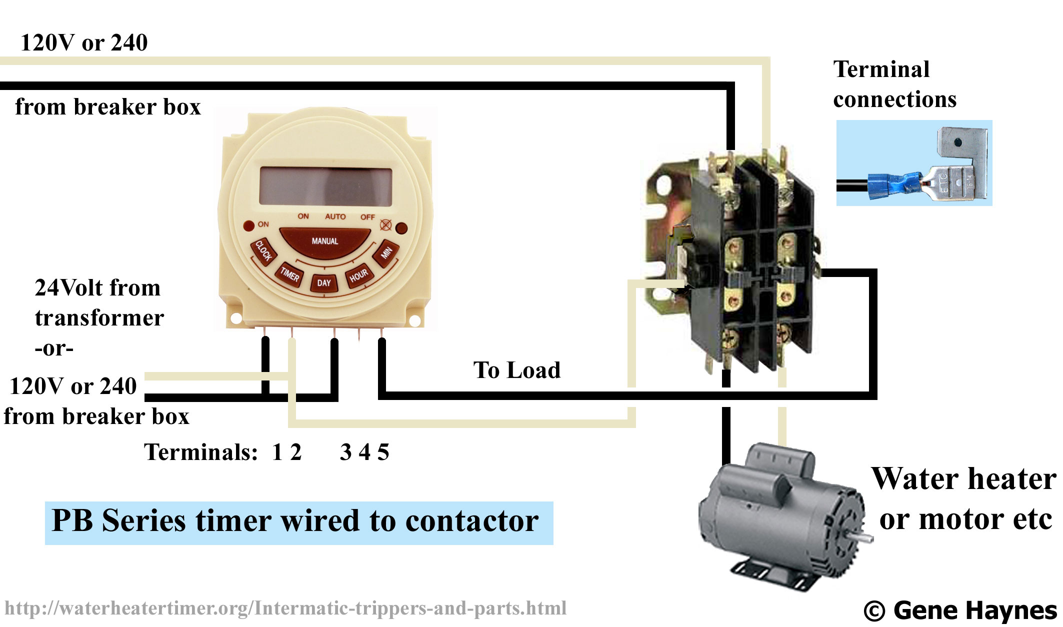
24 Volt To 12 Volt Dc/dc Converters Heavy Duty And Military Grade 24 Volt Transformer Wiring
Contactor coil wiring diagram.wiring diagram book a1 15 b1 b2 16 18 b3 a2 b1 b3 15 supply voltage 16 18 l m h 2 levels b2 l1 f u 1 460 v f u 2 l2 l3 gnd h1 h3 h2 h4 f u 3 x1a f u 4 f u 5 x2a r power on optional x1 x2115 v 230 v h1 h3 h2 h4 optional connection electrostatically shielded transformer.

120v 24v coil transformer wiring diagram. Control transformer, 120v ac, 240v ac, 24v ac, 75 va. A.on a call for cooling, the thermostat signals for the heating control valve to modulate toward the closed position. Connect white and black wires to 120v input.
Otherwise, the arrangement will not work as it. Ok, the transformer has a 24 volt secondary. *transformers 15 kva through kva are equipped with a volt lighting tap.
120v 24v transformer wiring diagram schematic mars transformers, transformer wiring diagrams vivresaville com, low voltage transformers farnell element14, 12v to 120v inverter circuit wiring diagrams, 12v to 120v voltage inverter circuit circuit wiring diagrams, wiring diagram 480 120v potential transformer best place, three phase transformers dongan, 24 volt. A great general purpose universal generic class 2 transformer with 24v coil. Each motor will be wired differently according to wiring diagram found on evaporator coil 120v motors 120v.
This heavy duty 40va transformer can be used in most all types of hvac units. Unit must be grounded 4. If you have any questions regarding these wiring diagrams or are having any difficulty correctly installing our transformers, please contact hps customer service or technical support in the u.s.
120v to 24v transformer wiring diagram. 480v to 120v transformer wiring diagram wiring diagram is a. Hps imperator tm industrial control transformer wiring diagrams issue date:
Connect red and green wires to 24v output. Catalog page # 206 206. After mounting, be sure you can safely close all doors a
Each part should be set and connected with other parts in specific manner. V to v transformer wiring diagram in v v. For motor amps see rating sticker on outside of unit 5.
Acme electric u milwaukee, wi u 800.334.5214 u acmetransformer.com 125 generalgeneral electrical connection diagramsacme® transformer™ wiring diagrams primary: The fully encapsulated coil eases wire routing around the transformer, and provides durable construction. Primary coils in series in the first diagram antrim this means connecting the white and black together, the part of a series.
However, the secondary also has a ct (center tap) so between either blue wire and the yellow (ct) you will measure 12 volts. Transformer universal 24 vac 75 va 120 208 240 480 volt. Connect white and red wires to 208v input.
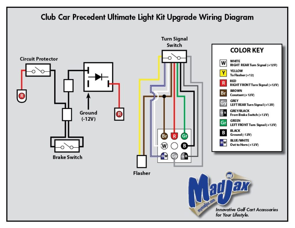
Connect white and orange wires to 240v input. Pin on electric golf cart. Use copper conductors only 3.
120v to 24v transformer wiring diagram transformer wiring diagram electric power amp transmission, wiring diagram for a 240v ac to 24v dc transformer, step down transformer electroschematics com, single phase transformer wiring connection best place to, wiring diagrams 3 phase step down transformer 277v to, wiring a 120v to Transformer wiring a 120v to 24v, special wiring wiring guide application information and wiring diagrams for belimo products a closer look the belimo difference basic electricity understanding wiring diagrams analog outputs wiring diagrams for belimo products applications specifications 24 vac transformer line volts 1 com mon 2 hot af24 us. Wiring diagram arrives with several easy to adhere to wiring diagram instructions.
750 va transformer has 2, 20amp breakers green wire for grounding outer sheath of each mat wire tap 1, black wire to. Valve 120v 120v 24v ac 120v notes: Control transformer wiring diagram v to v new v v.
Connect ahu line 2 to the supplied transformer according to the unit voltage. Connect the wires above to the relay per the wiring diagram, figure 1. These instructions will likely be easy to comprehend and apply.
Thus the center tap is common ) volts to either of the blue wires. That is 24 volts between the two blue wires of the secondary. Country of origin is subject to change.
It really is intended to aid all the typical user in building a suitable program. Lrc recommends cycling solenoid valve with motor 2. Ta series open core & coil industrial control transformers ta series open core & coil wiring diagrams group a group b group c x2 x1 h1 h3 h2 h4 24v h1 h2 240v 120v h3 h4 h1 h3 h4h2 x2 x1 120v 115 110 h1 h3 h2 h4 h1 h2 480v 460 440 h3 h4 h1 h3 h4h2 240v 230 220 x1 100v 95 90
Connect red and green wires to 24v output. 120v to 24v transformer wiring diagram 24 volt transformer wiring diagram images and photos, wiring diagram for a 240v ac to 24v dc transformer, 120v to 24v transformer wiring diagram, 12v to 120v dc dc converter circuit wiring diagrams, how to wire a 24v transformer hunker, wiring toriodal mains transformers, c wire how to power the thermostat via an additional transformer,. October 2007 rev4 page 1 of 9
Do not use this diagram to wire motor.

120V To 24V Transformer Wiring Diagram For Your Needs

480v To 120v Transformer Wiring Diagram — UNTPIKAPPS
24v Transformer 120 To 24 Volt Wiring Diagram Soffast
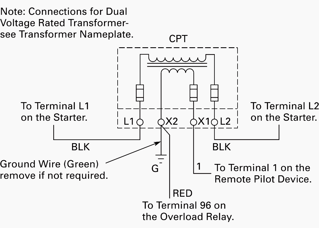
Wiring Diagram PDF 120v To 24v Transformer Wiring Diagram

24v Transformer 120 To 24 Volt Transformer Wiring Diagram BUSANABASEYYA
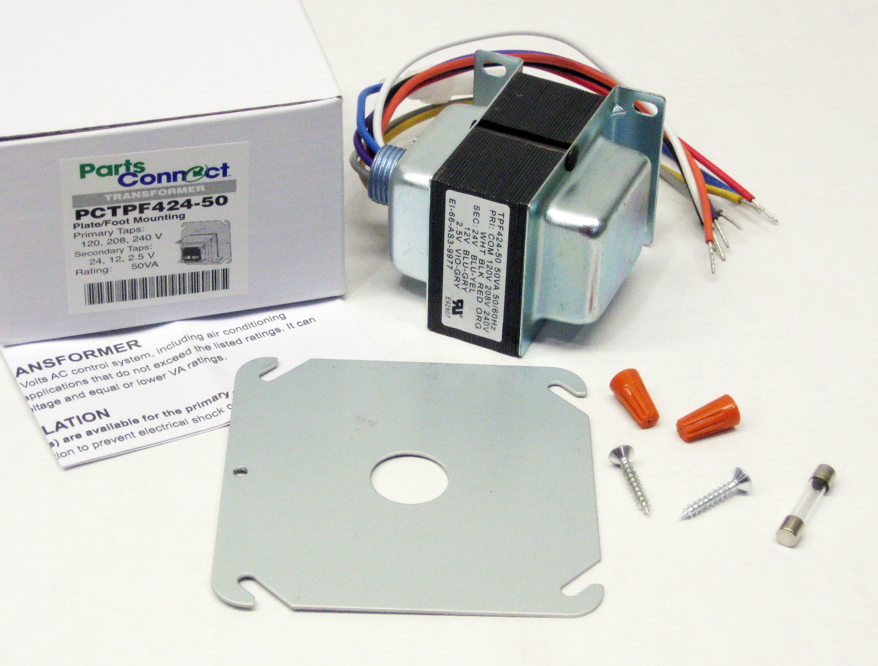
Furnace 24V Transformer Wiring Lb White Transformer 120v 24v Hog Slat A wiring diagram is a
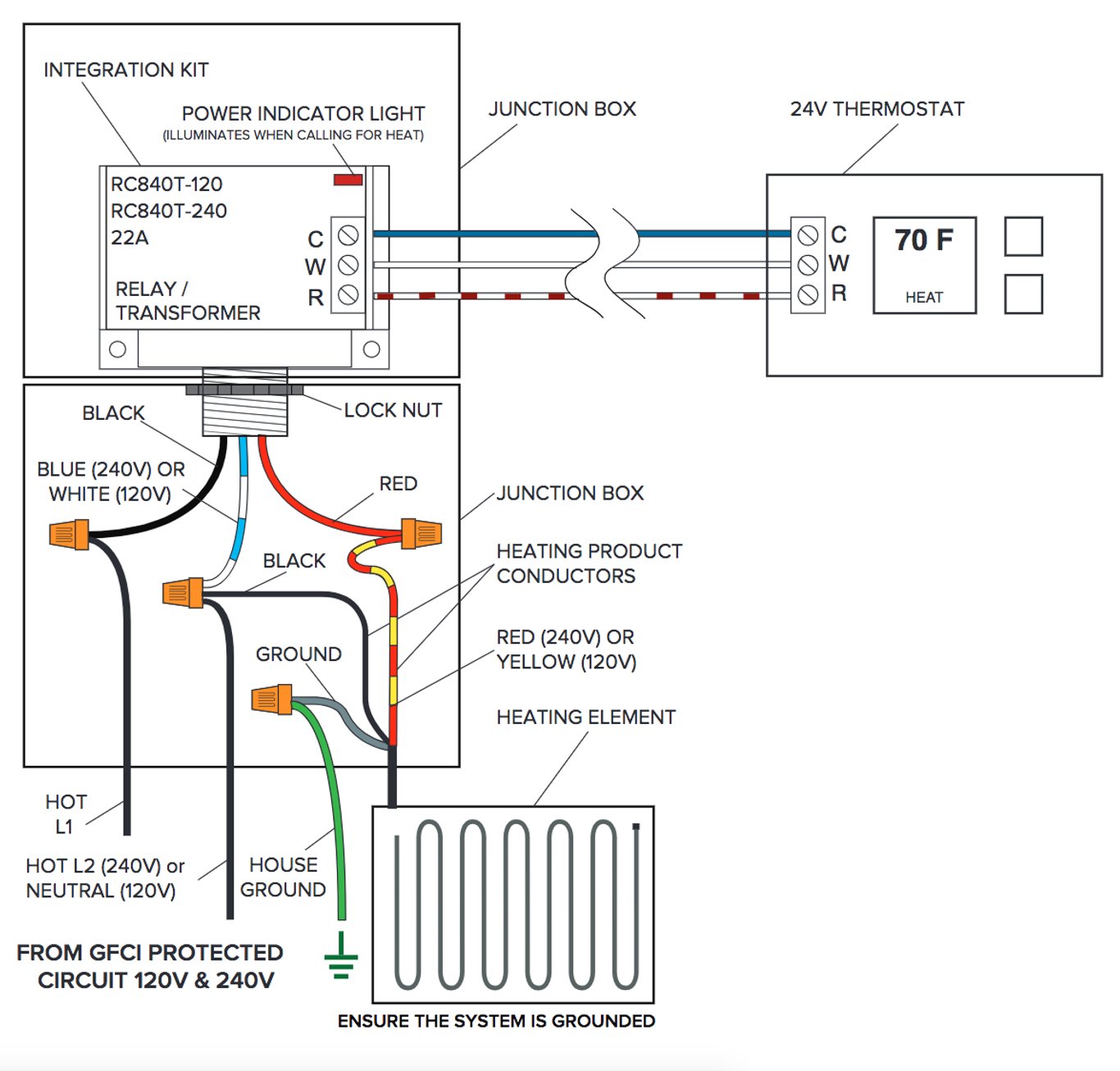
24vdc Relay Wiring Diagram Wiring Diagram

I have a 120V duct booster fan, a 24V thermostat, a 6AZT9 relay (from Grainger), and a 24V zone
circuit analysis How can I control a 120v, 1amp fan with a Nest thermostat? Electrical
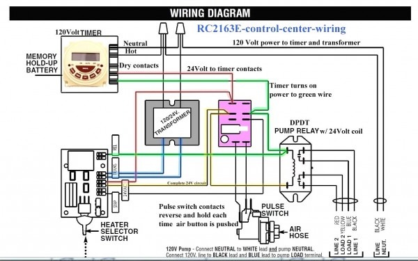
24 Volt Transformer Wiring Diagram
120V/24V Transformer for Brooders Hog Slat

Milivolt Systems w/ Modern Thermostats HVAC School
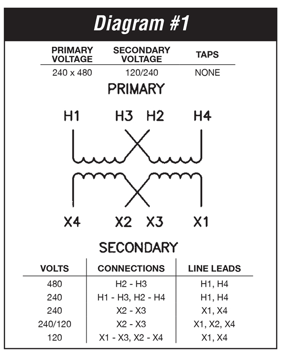
120V To 24V Transformer Wiring Diagram For Your Needs
Wiring Diagram PDF 120v To 24v Transformer Wiring Diagram
Hvac Transformer Wiring Diagram Download Wiring Diagram Sample

24 Volt Transformer Wiring Diagram
I have a 120V duct booster fan, a 24V thermostat, a 6AZT9 relay (from Grainger), and a 24V zone
